Step 1 - Tools & Equipment
|

|
If there is one thing that I would like to impress upon you, it is the benefit of using quality tools to do your work, The end result of any job is plainly due to the use of good quality tools. And there is also a saving by using good tools, because they last longer, and therefore you do not need to replace them as often.
- Stainless Steel Scissors
- Tweezers or other small no maring clamping device
- (Metric) Number Drills & Pin Vice
- Small Files
- Soldering Iron
- Hold & Fold Tool
- Solder & Flux or Solder Paint
- Snap-off Cutting Blade
- Fine Wet & Dry Paper
- 0.3mm brass wire (0.012")
- Burnishing Brush (Be very Careful)
- Selleys Acrylic Quickgrip
- Cutting Board
Lets get ready to Moddddddeeeeeelllllll
|
Step 2 - Preparing the Etch
|
|
- Re-Read the instructions (Yeah I Know!!!!!!)
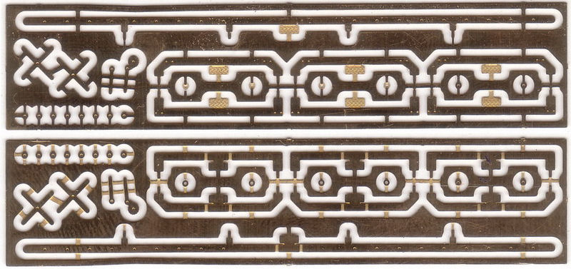
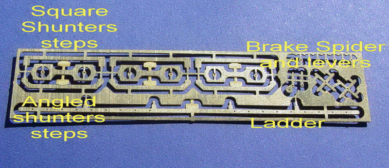
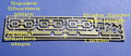
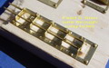
- This kit contains, ladder, shunters steps, brake spider wheels, release levers and packing rings. You have a choice of shunters steps, square or angled, use reference photos to make your decision.
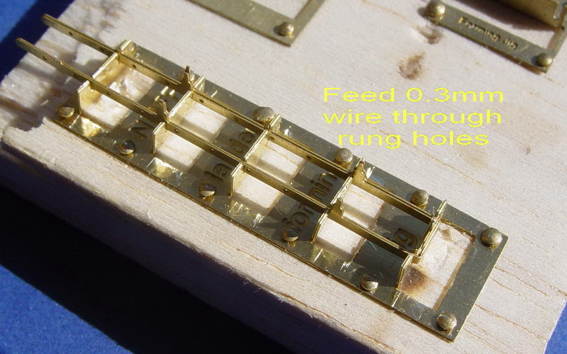
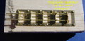
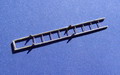
- The ladder can be formed in the ladder forming jig.
- Fold the ladder into a "U" shape and locate it in the jig after pinning the jig onto a piece of balsa.
- The ladder jig (KRM_HO_015A) is available as a seperate item free with every 6 pack, or for $2.50 on it's own
|
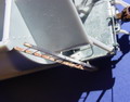
Step 3 - The Ladder
|

|
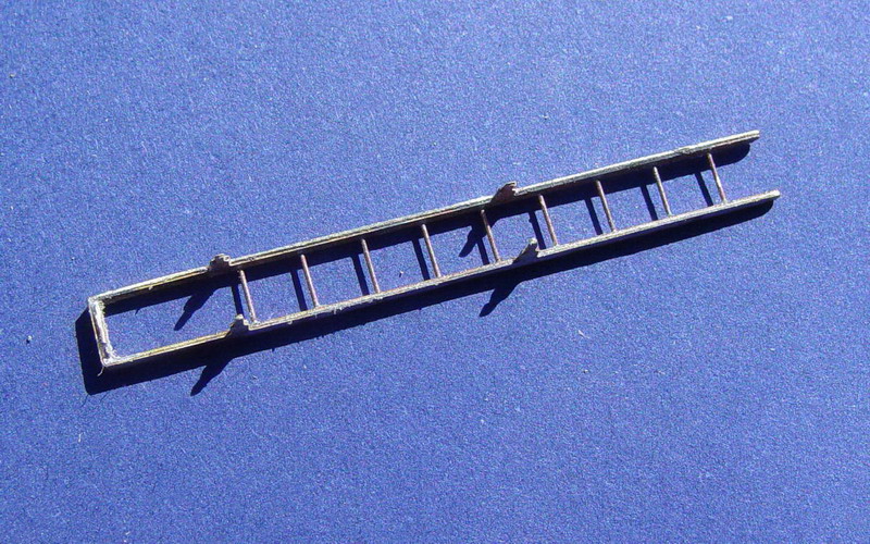
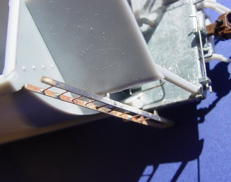
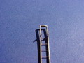
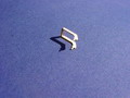
- Cut small lengths of 0.3mm wire and place them in the ladder rung holes. Solder one side of the rungs to start with.
- After one side is soldered, solder the other side, making sure the ladder is straight and square. Trim of the excess wire and and sand the sides smooth.
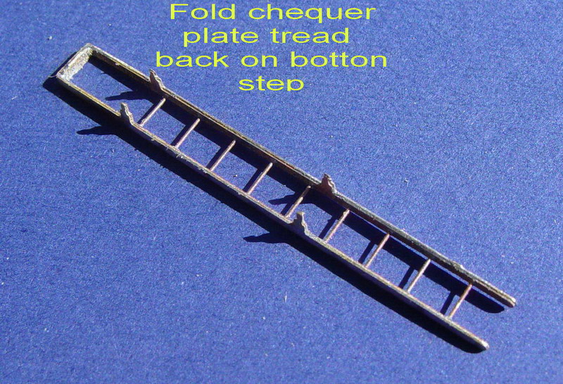
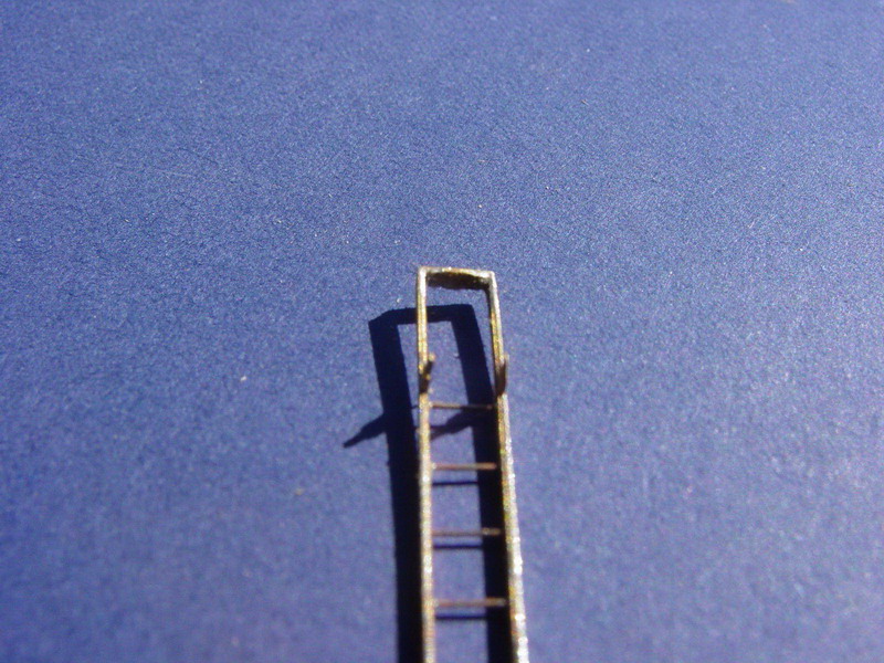
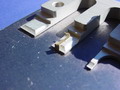
- Fold the chequer plate step back on itself so that the tread is sitting of the step, and solder in place.
|
Step 4 - The Shunters Steps
|
|
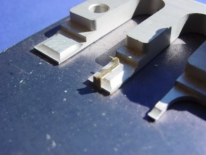
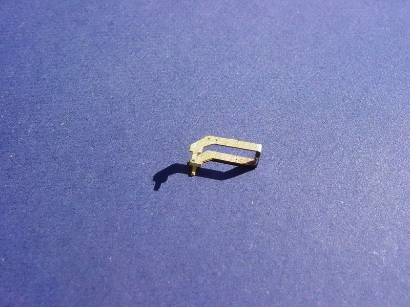
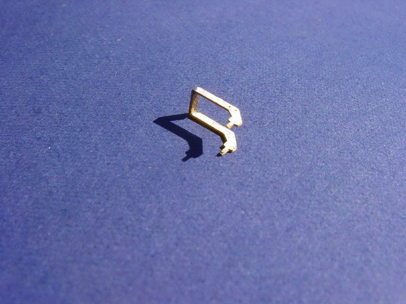
- Using the "Hold & Fold" tool, to fold the shunters steps.
- The shuntes steps are simply folded into a "U" shape and soldered after the chequer plate tread step is folded up and flat on the base of the step.
- The steps are located on the hopper using the tabs on the edge of the etchings.
|
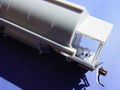
Step 5 - The Original Body.
|
|
- Remove the bogie screws and place the bogies and screws in a secure place.
- Glue all of the existing ladder, shunters steps and brake wheels into place.
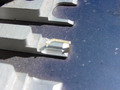
- Cut the parts from the model, leaving the plastic tabs in the holes on the hopper.
- Add more glue to the plastic plugs and file smooth. Also file away the molded release levers on the alloy castings.
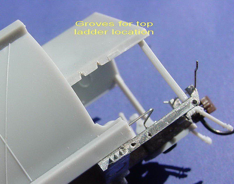
- Using a 0.4mm drill, drill holes in the plastic plugs, as the brass parts will need to be glued into these holes.
- The upper ladder supports, should have slight grooves to locate the ladder. These may need to be filed to open them up ever so slightly.
|
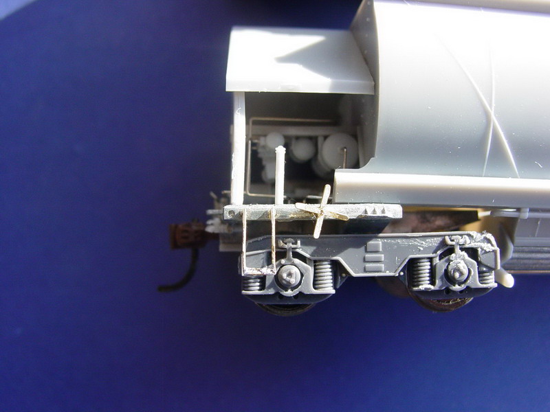
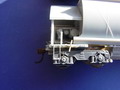
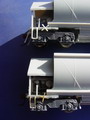
Step 6 - The Brake Gear
|
|
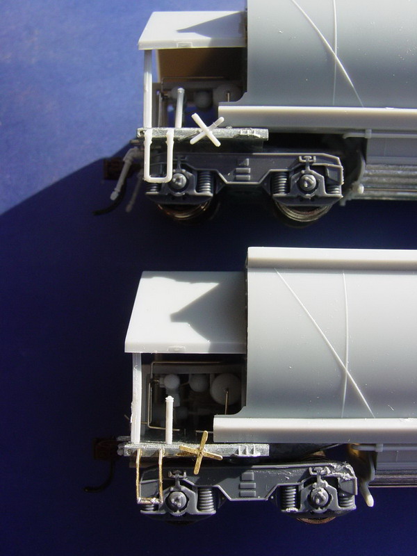
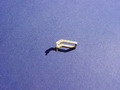
- Use the original parts to ensure the correct orientation of the release lever with ratchet.
- The brake gear is fitted into holes drilled into the metal body. Be careful when drilling the cast metal, as drill can easily be broken in this material.
- Place a small length of 0.3mm wire into the holes with a dab of supaglue and allow to dry.
- Cut a packing washer from the fret and fit this washer onto the wire, then place the release lever onto the wire with the handle facing the end of the vehicle, finally locate the brake spider onto the release lever.
- Superglue the completed brake setup together, then remove any excess wire, outside the brake spider.
|
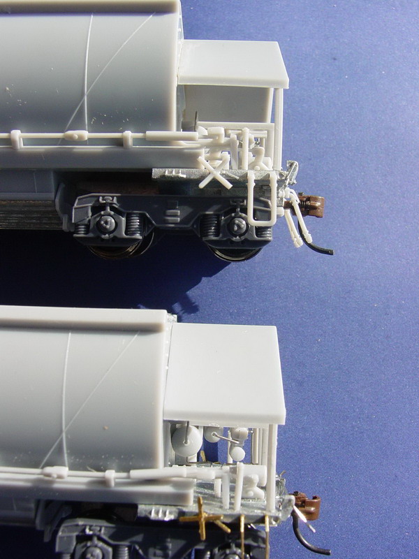
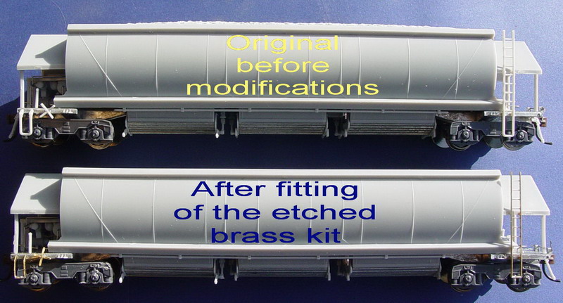
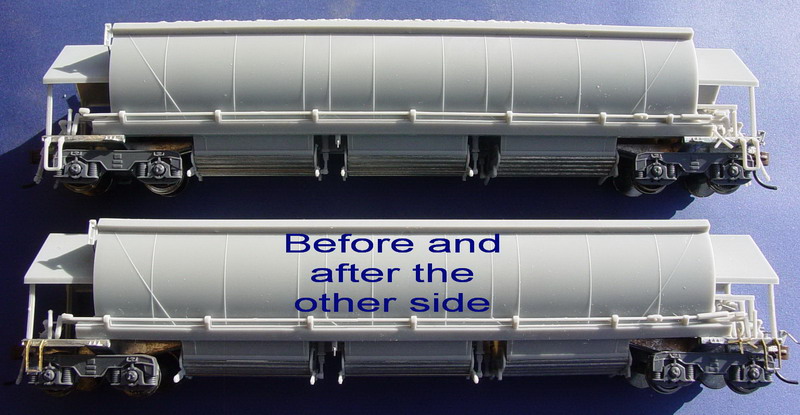
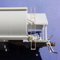
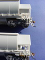
Step 7 - The Finished Look
|


|
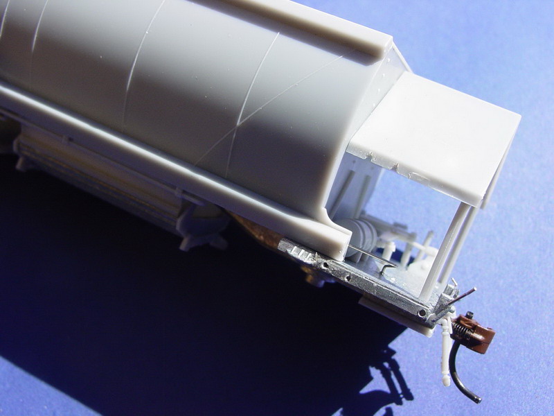
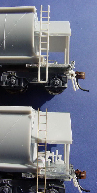
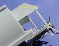
- The comparison of the before aand after photos allows you to make up your own mind.
- Finish the model as required by using prototype photos to gain information on how the model sould look.
|