Step 1 - Tools & Equipment
|

|
If there is one thing that I would like to impress upon you, it is the benefit of using quality tools to do your work, The end result of any job is plainly due to the use of good quality tools. And there is also a saving by using good tools, because they last longer, and therefore you do not need to replace them as often.
- Stainless Steel Scissors
- Tweezers or other small no maring clamping device
- (Metric) Number Drills & Pin Vice
- Small Files
- Soldering Iron
- Hold & Fold Tool
- Solder & Flux or Solder Paint
- Snap-off Cutting Blade
- Fine Wet & Dry Paper
- 0.3mm brass wire (0.012")
- Burnishing Brush (Be very Careful)
- Selleys Acrylic Quickgrip
- Cutting Board
Lets get ready to Moddddddeeeeeelllllll
|
Step 2 - Preparing the Etch
|


|
- Re-Read the instructions (Yeah I Know!!!!!!)
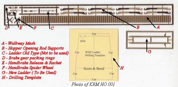
- Do not use the ladder (C) provided with the original kit, but instead use the superseded ladder (G) supplied separately. (Refer to top photo at left)
- Using a 0.3mm drill, clean out the holes in the ladder stiles (G), You will note that the superseded ladder (G) has the feet and stand-offs as a part of the ladder etch. (Refer to bottom photo at left)
- With a 0.4mm drill, clean out the holes in the brake spiders (F) and brake release levers (E).
- Using a sharp pointed pair of stainless steel scissors cut the components out of the fret, with the scissors at a 45-degree angle against the actual component. This allows most of the tab to be removed when cutting, minimising the need to clean up later. (Do be careful with the walkway and the ladder so as not to warp, bend or damage any of these components)
- Be carful when cutting out the Hopper Door Opening Rod Supports (B), and keep them in pairs, as they need to be folded together. It is probably a good idea to remove them one set at a time and solder or glue them together as you remove them, so as not to loose or damage the parts.
|
Step 3 - The ladder
|


|
- The ladder for the WHX (refer to top photo at left) is mounted on the same end as the slack adjuster. The ladder (G) comes with a cardboard template, to assist in drilling and locating the ladder.
- The ladder can be folded (refer to 2nd photo at left) and then the rungs (0.3mm brass wire - not supplied) locted in the holes in the stiles and soldered together.
- I use Carrs 188 solder paint and place it on the outer section of wire and heat the wire so that the solder paint flows toward the hole, and capillery action completes the solder joint.
- The excess wire and solder is then removed with fine files and sanded smooth with wet & dry paper. Wash the finished ladder thougherly in warm soapy water and allow to dry so that any excess flux is removed. Fold the feet at the base of the ladder IN at 90 degs to the ladder stiles. (refer to 3rd photo at left)
- Locate the cardboard drilling template on the bulkhead of the hopper . Notch out the template around the slack adjuster bracket (refer to the bottom photo at left). Hold the template in place and using a 0.4mmm drill, drill the locating holes in the positions shown on the template. Check that the ladder fits into the holes and open the holes out if the ladder is tight. The ladder can be placed in a secure place until it is ready to be assembled.
|
Step 4 - The Hopper Opening Rod Supports.
|


|
- The Hopper Door Rod Supports supplied with the kit are just lumps of plastic, the etched parts (B) are used to replace these and provide a place to locate a rod as per the prototype (refer to top photo at left) and to also give a 3D appearence.
- The etch parts are a 180 degree fold, and only allow ONE BEND, so get it right or there is much more work than necessary to get them together. Remove the sets one at a time from the fret and work on them as you remove them, please note that the sets are directional, so refer to photos for the correct direction of the supports.(refer to 2nd photo at left)
- Fold the etches together so the the smooth surfaces fold on to each other.(refer to 3nd photo at left)
- Ensure that the parts are aligned, place a small anount of solder paste between the parts, clamp the parts with tweezers and apply the iron to the parts to solder them together.
- Alternatatively, the parts can be glued together, if you prefer.
- Clean up any excess solder and any tab material from the fret with fine files and sand smooth with wet & dry paper. Wash the parts in warm soapy water and allow to dry.
- If you would like to add more detail to the supports, you could make up the hopper door opening rods and fabricate them using photos of the prototype.(refer to bottom photo at left) The supports were designed to accept 0.5mm wire for this purpose.
- The supports are glued to the base of the hopper bays in the same location as the origianl plastic pieces.
|
Step 5 - The Brake Gear
|


|
- The brake gear consists of the handbrake spiders (F), the ratchet and release levers, and a couple of packing rings (D)
- The parts are fitted to the existing brake support pieces (refer to top photo at left)
- Fill any holes in the plastic and use the etches as templets for drilling new holes (0.4mm) for the wire to go through to support the brake parts. Use the rings to pack out the brake parts, allowing them to give a 3 dimensional look.(refer to bottom photo at left)
- Place 0.4mm brass wire into the etches and through the plastic supports and the plastic gearbox. Solder or glue the brake spider wheels to the brass wire. If you feel inclined to take your time, you could allow the brake spiders to free wheel (spin).
- Clean up any excess solder/glue with warm soapy water and allow to dry
|
Step 6 - The Walkway
|


|
- The walkway is a see through type, and you need to be careful with handling the etch.
- Lightly sand (with fine wet @ dry paper) the edge of the etch, to remove any sign of tabs, and the cusp.
- Fit the ladder to the end of the bulkhead, and glue into place. (refer to top photo at left)
- The walkway etch is fitted so that it is aligned with the ladder (refer to centre photo at left)
- The walkway is glued to the exsisting plastic supports on the vehicle. I use Supaglue for this job, however, you may prefer to use another type of glue, it is your choice. No matter which glue you use, you must use it sparingly, so as not to fill any of the holes in the see-through walkway. (refer to bottom photo at left)
|
Step 7 - Finishing the Job - Hints & Tips.
|
.
|
- For painting the finished vehicle, I would prefer that you use the photos of the prototype in making this decision, as it is purely an individual action, based on what you see in real life. I prefer to weather these vehicle, as they were only ever in a new condition ONCE in their life, from that time on, they became grubby, dirty, rusty & damaged and even had graffiti on them.
- There is much more that can be fitted to these vehicles to make them more complete, things such as handrails, brake clevis parts, and brake rods, wire parts to simulate brake piping, and so much more. The level of detail is only limited by the modellers IMAGINATION, and lets face it, THAT has NO LIMITS
- The next batch of this etch will have the old ladder removed and in it's place will be the bulkhead inspection hatches, and the main brake lever. and some smaller parts that may enhance the vehicle even more. These parts will also be available seperately for a minimal fee. This is based on the continual improvement principal, which I have adopted.
- If you have any commnets, or ideas as to how I can improve this kit, please don't hesitate to contact me
by email or phone on 61 2 46772462
|


