Step 1 - Tools & Equipment
|

|
If there is one thing that I would like to impress upon you, it is the benefit of using quality tools to do your work, The end result of any job is plainly due to the use of good quality tools. And there is also a saving by using good tools, because they last longer, and therefore you do not need to replace them as often.
- Stainless Steel Scissors
- Tweezers or other small no maring clamping device
- (Metric) Number Drills & Pin Vice
- Small Files
- Soldering Iron
- Hold & Fold Tool
- Solder & Flux or Solder Paint
- Snap-off Cutting Blade
- Fine Wet & Dry Paper
- 0.3mm brass wire (0.012")
- Burnishing Brush (Be very Careful)
- Selleys Acrylic Quickgrip
- Cutting Board
Lets get ready to Moddddddeeeeeelllllll
|
Step 2 - Preparing the Etch
|


|
- Re-Read the instructions (Yeah I Know!!!!!!)
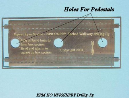
- (Refer to top photo at left)The jig as supplied - Using a 0.55mm drill, clean out the holes in the jig ready for drilling.
- Remove the jig from the fret using a small pair of stainless steel scissors.(Refer to 2nd photo at left)
- To remove the tabs (without filing) use the scissors at an angle of 30- 45 deg, cutting closely to the etch. This should give a relatively clean finish.(Refer to bottom photo at left)
|
Step 3 - Folding The jig
|


|
- Fold the inner fold line (perforated to make it easier to fold) to 90 Degs. Ensure that it is square to the top face. The "Hold & Fold" tool can be used for this job.(Refer to top photo at left)
- Fold the outer fold to form a box section, and make sure that the box section is square.(Refer to 2nd photo at left)
- Fold the end tabs in to square up the box section, and solder the joints after ensuing that the whole jig is square.(Refer to bottom photo at left)
|
Step 4 - Mounting the jig
|


|
- After following the instructions in the walkway kit and preparing the body for drilling. Place the jig onto the body over the pedestals, with the large arrow facing the extension landing side.(Refer to top photo at left)
- Place the filler caps on the pedestals securing the jig in place.(Refer to 2nd photo at left)
- Make sure that the jig is sitting nice and square onto the body.(Refer to bottom photo at left) The importance of this step cannot be over emphasized, as you will see shortly.
|
Step 5 - Drilling the Body
|


|
- The reason for the box section was to enable the jig to guide, firstly the pin and secondly the drill that drills the holes in the body to accept the walkway etch. To assist in the process, a brass lace pin is supplied in the kit and is used to act as a centre punch to give the drill something to bite into, and preventing it from wandering.(Refer to top photo at left)
- Making sure that the pin is square to the jig and body, mark each and every hole position through the drilling jig for the walkway legs. Take this step very steadily, as a pop mark in the wrong position will lead to the holes in the wrong positions and hence the legs not sitting square.(Refer to 2nd photo at left)
- Keep the jig on the model, and using a 0.5mm drill, locate the drill onto the marks previously provided by the pin. For now just mark the start of the holes. When all the holes have been marked, you can continue to drill through the body whilst keeping the drill square to the body. All of the holes are drill completely through the body except for the two end holes that are indicated.(Refer to bottom photo at left) The jig can now be removed from the body. HINT--- If you find it difficult to fit the legs of the walkway into the body you can drill the holes out using a 0.55mm or 0.6mm drill
|


