Step 1 - Tools & Equipment
|

|
If there is one thing that I would like to impress upon you, it is the benefit of using quality tools to do your work; the end result of any job is plainly due to the use of good quality tools. And there is also a saving by using good tools, because they last longer, and therefore you do not need to replace them as often.
- Stainless Steel Scissors
- Tweezers or other small no maring clamping device
- (Metric) Number Drills & Pin Vice
- Small Files
- Soldering Iron
- Hold & Fold Tool
- Solder & Flux or Solder Paint
- Snap-off Cutting Blade
- Fine Wet & Dry Paper
- 0.3mm brass wire (0.012")
- Burnishing Brush (Be very Careful)
- Selleys Acrylic Quickgrip
- Cutting Board
Lets get ready to Moddddddeeeeeelllllll
|
Step 2 - Preparing the Etch
|


|
- Re-Read the instructions (Yeah I Know!!!!!!)
- Make yourself familar with the etch components
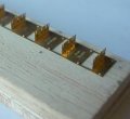
- Drill the holes on the side of the jig using a 0.5mm drill (refer to top photo at left)
- Check the sides of each section of the jig to ensure that the jig is completely etched through. If flash can be found, remove it with a sharp snap off blade. (Refer to top photo at left)
- The holes are used to locate the jig on a baseplate (My preference is Balsa) (Refer to middle photo at left)
- Slip a knife under each section to pry it upward, and once the panel is lifted slightly, you can finish bending the sections with the "Hold & Fold Tool" available form I R Models Refer to top photo listed under tools and equipment; the "Hold & Fold" tool is to the right of the pliers in the middle of the photo.
- Once the sections have been folded, try to keep them at 90 degrees (Refer to bottom photo at left)
- Using brass lace pins, available from KRM MISC 002 secure the jig to the timber, removing any excess brass pin from the underside of the timber
- The ladder jig is now ready for work
|
Step 3 - Working with the ladder
|


|
- The jig is designed to house 0.3mm thick brass ladder stiles which are available from the products page
- Clean out the rung holes on 2 stiles using a 0.3mm drill
- Remove the ladder stiles from the fret, using a sharp pair of stainless steel scissors (Minimising work by removing as much tab material as possible).
- Place the ladder stiles in the jig in the appropriate slots, depending on your ladder width (Refer to top photo at left)
- Locate a piece of 0.3mm brass wire (with overhang) into the top and bottom rung holes of the stiles and drag the stiles and rungs down so that the rung hits the vertical sections of the jig. This squares the stiles to the jig. (Refer to 2nd photo at left).
- Place 0.3mm wire into the ladder rungs and solder into place (do one side first). I prefer to use Carr's 188 solder paint. Simply place a dab of paint on the end of the rungs and heat with the soldering iron. The solder paint flows so that the joint forms through capillary action. (Refer to 3rd photo at left)
- Take the time to work your way down the ladder, leaving the rungs that are near the support brackets until later.
- Once all of the rungs are soldered in place move the ladder in the jig, so that you can solder the rungs into the remaining holes. (Refer to bottom photo at left)
- You need to be aware that the use of only enough solder paste is advised, to reduce the amount of clean up required.
|
Step 4 - The Clean Up
|

|
- You need to be very careful with the clean up of the ladder, as it can be easily bent and twisted.
- Once, all of the rungs have been soldered into place, cut away any excess wire.
- Using a fine file, file away the excess solder on the outside of the stiles, and use fine wet and dry paper to finish the job.
- If you have use the solder paste sparingly, there should be a minimum amount of solder on the inside of the ladder stiles. Carefully clean up what solder has built up.
- When the ladder has been cleaned up, wash it in warm soapy water to remove any trace of the flux from the solder paint (as it can be corrosive). (Refer to photo at left)
- The alternative to the solder paste is a home made solder flux by a friend of mine, which is available by contacting Keiran Ryan Models by email or phone on 61 2 46772462
|


